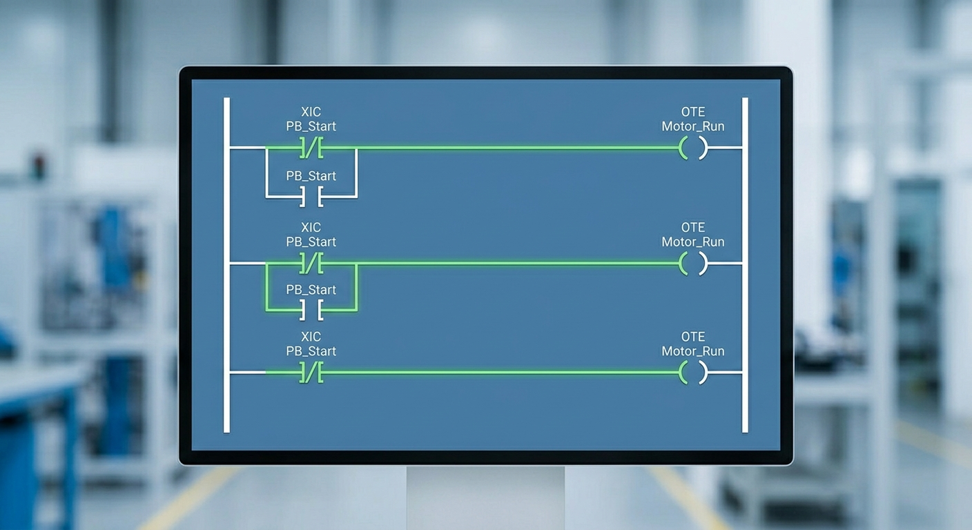
Ladder logic is a graphical PLC programming language that represents control decisions using rails, rungs, contacts, coils, and function instructions. Its visual relationship to relay circuits makes it practical for electricians, maintenance technicians, and controls engineers working on discrete machines.
Contacts and coils
A contact instruction evaluates a Boolean condition such as a sensor, pushbutton, permissive, or internal state. A coil writes a Boolean result to an output or tag. In a real machine, a rung may require guard status, drive ready, and an operator command before energizing a motor run request.
Series and parallel logic
Series conditions behave like AND logic: every condition must be true. Parallel branches behave like OR logic: one acceptable path can satisfy the rung. Clear grouping matters. A technician should be able to see which conditions are required and which are alternate recovery paths.
Timers, counters, and one-shots
Timers create controlled delays or detect a device that did not respond within a permitted time. Counters track parts or cycles. One-shot instructions act on a transition once rather than repeatedly during every scan. These tools are useful, but they should support an explicit sequence instead of hiding a machine state.
Interlocks and troubleshooting
Good ladder logic exposes why an output is off. Use descriptive permissive tags, alarm conditions, and state information. Avoid bypassing safety circuits with software contacts. For more on this boundary, read PLC interlocks and permissives.
Readable ladder logic
- Use consistent tag names and rung comments.
- Separate raw I/O from commands, states, and alarms.
- Keep sequence transitions visible.
- Document timers, units, and expected feedback.
- Test faults and recovery, not only the normal cycle.
For a broader programming workflow, see PLC programming basics. TechControl provides PLC programming and support for existing machine logic.
Ready to bring your project to life?
Contact Us